Harrison Cooling Towers
A cooling tower is a heat rejection device, which extracts waste heat to the atmosphere through the cooling of a water stream to a lower temperature. The type of heat rejection in a cooling tower is termed "evaporative" in that it allows a small portion of the water being cooled to evaporate into a moving air stream to provide significant cooling to the rest of that water stream. The heat from the water stream transferred to the air stream raises the air's temperature and its relative humidity to 100%, and this air is discharged to the atmosphere.
Evaporative heat rejection devices such as cooling towers are commonly used to provide significantly lower water temperatures than achievable with "air cooled" or "dry" heat rejection devices, like the radiator in a car, thereby achieving more cost-effective and energy efficient operation of systems in need of cooling.
Think of the times you've seen something hot be rapidly cooled by putting water on it, which evaporates, cooling rapidly, such as an overheated car radiator. The cooling potential of a wet surface is much better than a dry one.
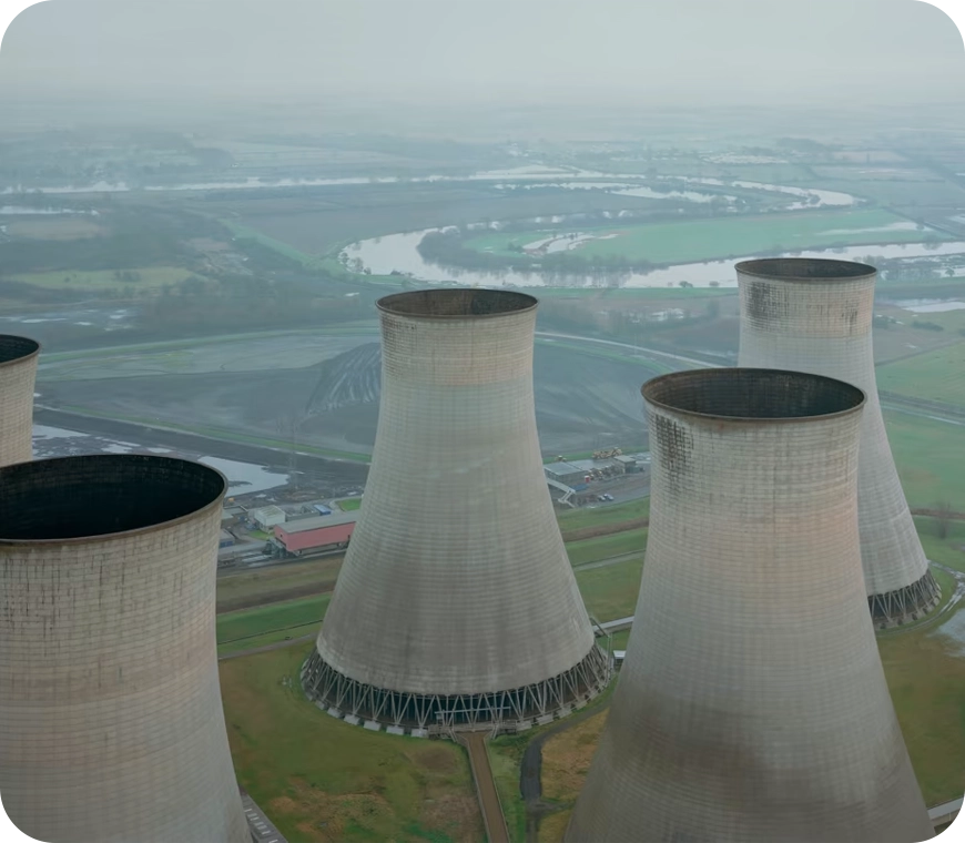
Common applications for cooling towers are providing cooled water for air-conditioning, manufacturing and electric power generation. The smallest cooling towers are designed to handle water streams of only a few gallons of water per minute supplied in small pipes like those might see in a residence, while the largest cool hundreds of thousands of gallons per minute supplied in pipes as much as 15 feet (about 5 meters) in diameter on a large power plant.
The generic term "cooling tower" is used to describe both direct (open circuit) and indirect (closed circuit) heat rejection equipment. While most think of a "cooling tower" as an open direct contact heat rejection device, the indirect cooling tower, sometimes referred to as a "closed circuit cooling tower" is nonetheless also a cooling tower.
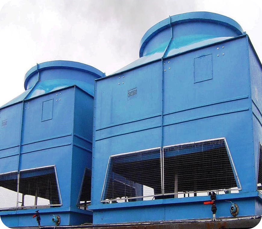
A direct, or open circuit cooling tower is an enclosed structure with internal means to distribute the warm water fed to it over a labyrinth-like packing or "fill." The fill provides a vastly expanded air-water interface for heating of the air and evaporation to take place. The water is cooled as it descends through the fill by gravity while in direct contact with air that passes over it. The cooled water is then collected in a cold water basin below the fill from which it is pumped back through the process to absorb more heat. The heated and moisture laden air leaving the fill is discharged to the atmosphere at a point remote enough from the air inlets to prevent its being drawn back into the cooling tower.
The fill may consist of multiple, mainly vertical, wetted surfaces upon which a thin film of water spreads (film fill), or several levels of horizontal splash elements which create a cascade of many small droplets that have a large combined surface area (splash fill).
An indirect, or closed circuit cooling tower involves no direct contact of the air and the fluid, usually water or a glycol mixture, being cooled. Unlike the open cooling tower, the indirect cooling tower has two separate fluid circuits. One is an external circuit in which water is recirculated on the outside of the second circuit, which is tube bundles (closed coils) that are connected to the process for the hot fluid being cooled and returned in a closed circuit.
Air is drawn through the recirculating water cascading over the outside of the hot tubes, providing evaporative cooling similar to an open cooling tower. In operation, the heat flows from the internal fluid circuit, through the tube walls of the coils, to the external circuit, and then by heating of the air and evaporation of some of the water, to the atmosphere.
Operation of the indirect cooling towers is therefore very similar to the open cooling tower with one exception. The process fluid being cooled is contained in a "closed" circuit and is not directly exposed to the atmosphere or the recirculated external water.
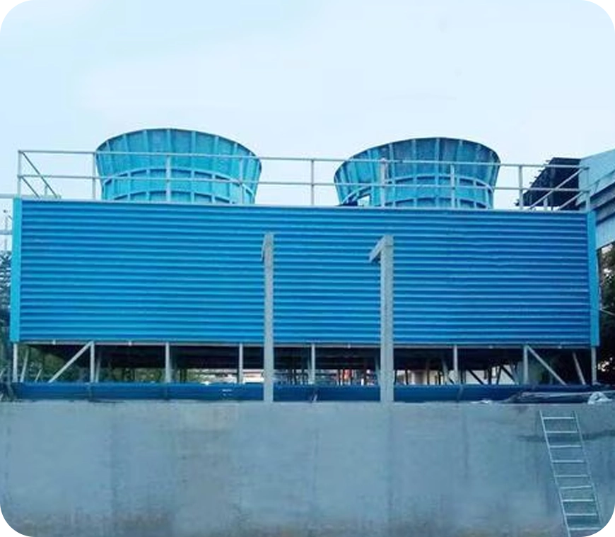
In a counter-flow cooling tower, air travels upward through the fill or tube bundles, opposite to the downward motion of the water. In a cross-flow cooling tower, air moves horizontally through the fill as the water moves downward.
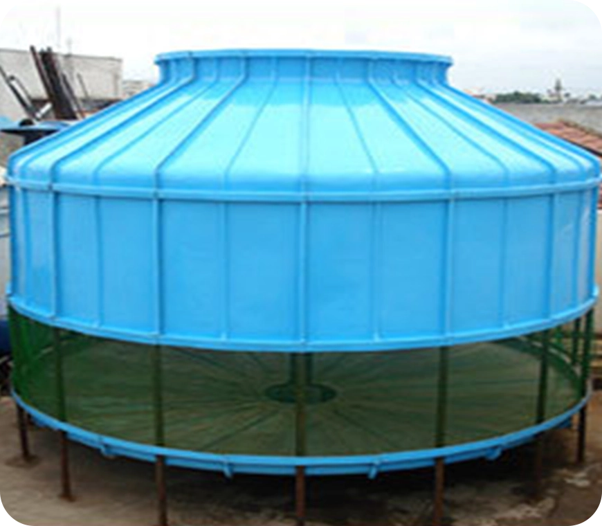
Cooling towers are also characterized by the means by which air is moved. Mechanical-draft cooling towers rely on power-driven fans to draw or force the air through the tower. Natural-draft cooling towers use the buoyancy of the exhaust air rising in a tall chimney to provide the draft. A fan-assisted natural-draft cooling tower employs mechanical draft to augment the buoyancy effect. Many early cooling towers relied only on prevailing wind to generate the draft of air.
If cooled water is returned from the cooling tower to be reused, some water must be added to replace, or make-up, the portion of the flow that evaporates. Because evaporation consists of pure water, the concentration of dissolved minerals and other solids in circulating water will tend to increase unless some means of dissolved-solids control, such as blow-down, is provided. Some water is also lost by droplets being carried out with the exhaust air (drift), but this is typically reduced to a very small amount by installing baffle-like devices, called drift eliminators, to collect the droplets. The make-up amount must equal the total of the evaporation, blow-down, drift, and other water losses such as wind blowout and leakage, to maintain a steady water level.
Some useful terms, commonly used in the cooling tower industry:
Drift - Water droplets that are carried out of the cooling tower with the exhaust air. Drift droplets have the same concentration of impurities as the water entering the tower. The drift rate is typically reduced by employing baffle-like devices, called drift eliminators, through which the air must travel after leaving the fill and spray zones of the tower.
The process of cooling tower is among the oldest known. Usually exposing its surface to air cools water. Some of the process is slow, such as cooling of water on the surface of a pond; others are comparatively fast, such as spraying of water into air. These processes all involve the exposure of water surface to air in varying degrees.
The heat transfer process involves:
Heat transfer is due to latent heat and 20% of sensible heat. Theoretical possible heat removal per pound of air circulated in a cooling tower depends on the temperature and moisture content of air, which is its wet bulb temperature. Ideally, wet bulb temperature is the lowest theoretical temperature to which water can be cooled. Practically, the cold water temperature approach.
Blow-out - Water droplets blown out of the cooling tower by wind, generally at the air inlet openings. Water may also be lost, in the absence of wind, through splashing or misting. Devices such as wind screens, louvers, splash deflectors, and water diverters are used to limit these losses.
Plume - The stream of saturated exhaust air leaving the cooling tower. The plume is visible when water vapor it contains condenses in contact with cooler ambient air, like the saturated air in one's breath fogs on a cold day. Under certain conditions, a cooling tower plume may present fogging or icing hazards to its surroundings. Note that the water evaporated in the cooling process is "pure" water, in contrast to the very small percentage of drift droplets or water blown out of the air inlets.
Blow-down - The portion of the circulating water flow that is removed in order to maintain the amount of dissolved solids and other impurities at an acceptable level.
Leaching - The loss of wood preservative chemicals by the washing action of the water flowing through a wood structure cooling tower.
Noise - Sound energy emitted by a cooling tower and heard (recorded) at a given distance and direction. The sound is generated by the impact of falling water, by the movement of air by fans, the fan blades moving in the structure, and the motors, gearboxes, or drive belts.
In olden times, when industries were few and large, they were located near riverbanks. The water for the process cooling used to be drawn from the river and the hot water was again pumped back into the river. With the passage of time, more industries came up and cooling ponds were used for cooling the process machinery. In the cooling pond, either a fountain or spray tower was sufficient to cool the water and hence a larger pond would be built in the premises. When the space became less and costlier and discarding/wasting water became a criminal offense, every care is taken to reuse the water which is used for cooling the process machinery, that is where the Cooling Tower found its application. The first type of Cooling Tower is used for cooling the hot water, which is coming out of the process plant in chemical industries, diesel gensets, compressors, and plastic processing machines. Essentially, this is a heat exchanger. Water is the cheapest and best medium available on earth for heat dissipation.
Hence from the beginning of the industrial growth, water is used for dissipating heat from equipment and machinery which gets heated up while working.
The tower was a Natural Draught Cooling Tower made from treated Timber. In this case, the main header and branches do water distribution over an entire area of the cooling tower through the spray nozzles. The spray nozzles break the water into small particles where the evaporative cooling takes place. In this case, the area required for installation is larger and the cooling is dependent on environmental conditions like wind velocity and the direction of the wind. For optimum cooling, the wind velocity has to be within 5 to 8 miles per hour. If the velocity is more, the cooling will be better, but the drift losses would be more. On the other hand, if the wind velocity is less, the cooling efficiency of the cooling tower would come down, and the drift losses would also be lesser.
The second stage in the evolution of the Cooling Tower is the mechanical draught Cooling Tower, where the mechanical device like fan or blower is used for creating/increasing the airflow. In these mechanical draught Cooling Towers, the cooling tower interior is filled with filling material, which will increase the available heat transfer area. Mechanical draft Cooling Towers are sub-divided into:
Forced Draft Cooling Tower: In the case of a Forced Draught Cooling Tower, the fan is mounted on one of the sides of the cooling tower, and most of the air escapes through the other side. The hot water tray is placed on the top of the cooling tower, and the water falls through splash nozzles onto the fillings inside, where it comes in contact with the cold air from the fan. This air takes away the heat from the water and escapes through the drift eliminator. In timber cooling towers, the drift eliminator plays a major role in preventing water loss by way of drift loss. The moisture-laden air comes in contact with the drift eliminator, and any water droplets carried with it are condensed into water drops and fall back into the cooling tower. This cooling tower is used for specific applications where the moisture should not come in contact with the fan and motor assembly.
This is the widely used and widely accepted Cooling Tower in Timber Cooling Towers. In this case, the fan is mounted on top of the Cooling Tower. Air is drawn from the side inlet louvers, and the moist air escapes through the fan. Timber or PVC fills are placed inside to increase the heat transfer area. The hot water tray is located on top of the cooling tower next to the fan assembly. The water is distributed onto the fills by splash nozzles. The air is drawn in by the induced draught fan, and heat transfer takes place when it comes in contact with the hot water in the fills. The hot air, saturated with water vapor, escapes through the fan orifice. Here again, the drift eliminator plays a role in trapping the water droplets from the outgoing moist air.
In the case of Timber Induced Draught Cooling Towers, there are two types:
FRP cooling towers were introduced in the 1970s and were widely accepted in India in the 1980s.
The advantage of FRP (Fiberglass Reinforced Plastic) is that it can be molded into any contour we need. While developing the FRP bottle-shaped cooling tower, care was taken to eliminate dead air pockets and increase the water-to-air exchange ratio. In the case of timber cooling towers, this was not possible, as the cooling towers were made in rectangular shapes.
In the FRP bottle-shaped cooling tower, the hot water is distributed by a rotary sprinkler, which is located below the fan. The sprinkler rotates at a speed of 16 to 20 rotations per minute. The PVC fills are placed immediately below the rotating sprinkler, and the hot water is distributed throughout the fill area.
The FRP cooling tower is lightweight compared to its wooden counterpart. The entire weight is distributed equally on four or five pedestals. Hence, the masonry work is minimized, and it can be installed on the roofs of buildings. Additionally, the cooling tower is stable and does not require costly harnessing arrangements.
In the case of FRP induced draught cooling towers, the airflow is induced, and the water flows counter (opposite) to the airflow. This design makes the FRP cooling tower more efficient than the timber cooling towers. The honeycomb PVC fills used to increase the heat transfer area have about 82 sq. ft. of area in one cubic foot. Hence, the cooling tower can be made compact, occupying less space.
The fan is made from cast aluminum LM-6 material, and it is balanced statically and dynamically for vibration-free performance. In FRP cooling towers, the motor used is a low RPM one, with speeds of 960/720/600 or 500 RPM, depending on the size of the cooling tower. This eliminates the need for gear reducers and connecting drive shafts. Since there are no gear reducers, the vibration of the cooling tower is reduced considerably.